Multi Room Audio - part III
23 Mar 2019At this point, I’d got a prototype working and understood how all the key pieces of my system will hang together. The next major phase is to expand the number of players and work out exactly where all the components are going to be located and how they are going to be cabled together.
Because of the decision to use the transformer and power splitter, I was going to have to colocate all the players that had IQaudIO boards and attached to passive speakers. On the plus side, power and networking would be simpler as I was already sorted for power and I could attach them all to a small gigabit network switch. But the speakers would be some distance from the unit and require lengthy cable runs.
There was also one player which would connect to the soundbar in the lounge which had different power input (standard Pi USB) and signal output (HDMI) requirements. That needed some thinking about too.
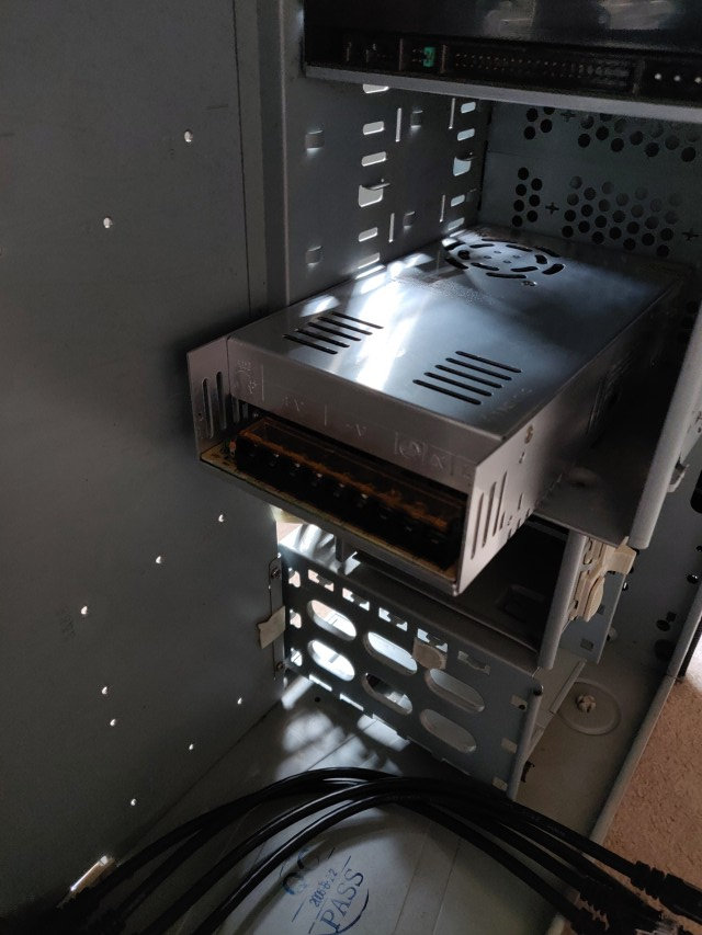
Equipment Case
One of my goals had been to reuse as much existing kit as I could and there was quite a lot of old computing equipment in the attic. An old PC was retrieved and completely stripped of its components leaving just the empty case (and the DVD drive as I didn’t have a blanking panel to replace it). It was far too big really but it would do the job of housing the Pis, the transformer and the network switch; the latter needing a bit of creative work to secure it in place :)
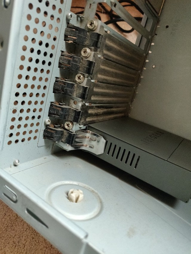
I mentioned earlier that I had a few concerns about the ability of the power splitter to carry sufficient current to the 5 output cables, especially if all of them were drawing the maximum amount. It just looked far too slim. To solve this, I now cut all 5 of the output cables off close to the join and discarded the common bit of the cable. That was replaced with a normal plastic block connector and some blue/brown wire from inside a spare bit of mains flex. The (now separate) 5 barrel connector cables were all stripped and then I twisted all the reds together and all the blacks together to insert into the block connector. You can see the outcome of that in the next picture.
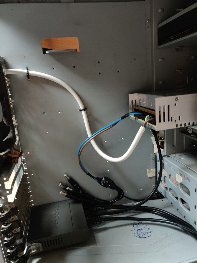
Being a bit paranoid with the electrical work, I once again tested the barrel ends of all 5 connectors for correct DC voltage. Still OK.
Pi Rack
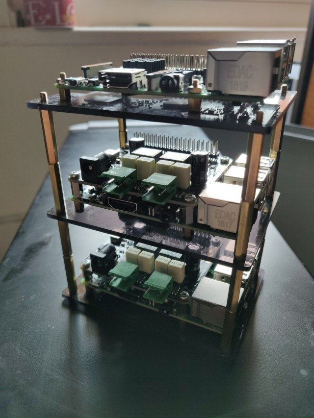
With one of a few racking kits that you can buy for RasPi these days, I created a stack of players. It needed a bit of extra height because the rack kit wasn’t designed for DigiAmp+ boards sitting on top of the Pi and that adds enough height that the outer standoffs between the plastic bases weren’t long enough. They had to be doubled up. When this pic was taken, and a few of the later ones, I was still waiting for one more DigiAmp+ to arrive as one had turned up DoA and needed to be sent back for replacement.
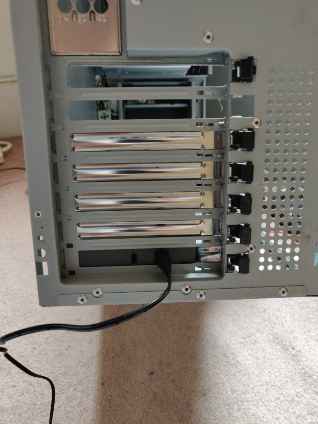
With the rack held in place with a number of cable ties to the case, it was possible to plumb it all together and see how it was shaping up. At this point, you can see in the picture that the top most player has an HDMI output which was the one intended for the soundbar in the lounge. My intention was to house the whole thing in the cabinet under the TV and so this would have been the easy part of the cable work. Not quite how it turned out in the end.
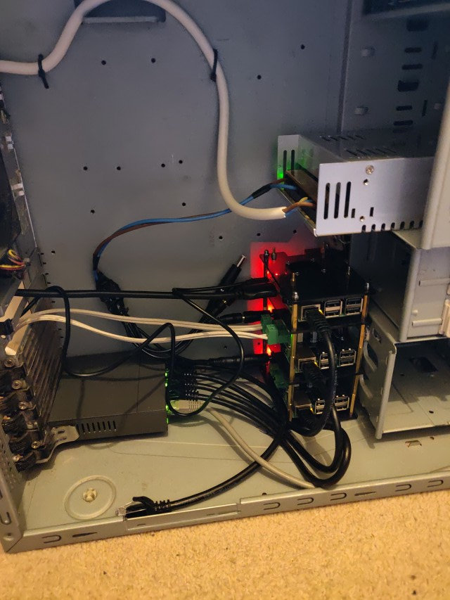
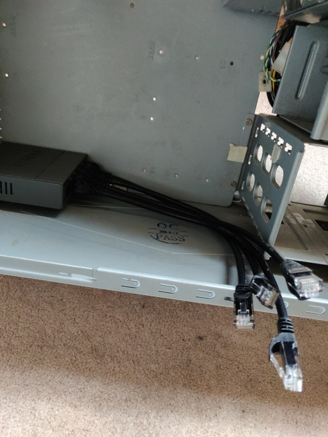
Everything so far working. Pis have network (albeit with a cable coming out of the case and into the main ethernet switch under the desk, still had to think about how that was going to work later on) and power and I’ve used my scrappy old speaker wire to test output to one of the pairs of passive speakers. In the next pic a newly bought pair of Q Acoustics bookshelf speakers are also added in for further testing and using the much higher quality speaker cable that I planned to use everywhere. The speakers were bought based on customer reviews for ones in that sort of price range, but although they’re OK, they cannot hold a candle to my 30 year old Kef C25’s - also shown - or the larger Mission 762 pair that we already owned.
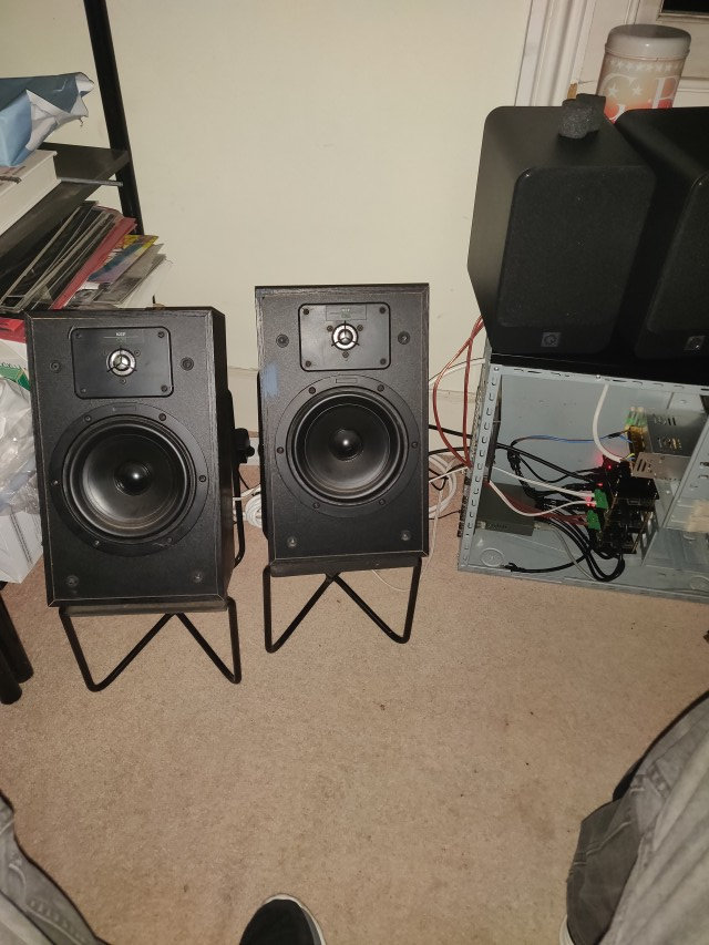
It’s not quite “multi-room” yet, but it was certainly taking shape. It was nice to be able to play around with the music output to the different speakers from the LMS server software and at this point I was able to test for the first time that the synchronisation of the different players worked as designed. It did so, very nicely and with absolutely no perceptible lag in the sound across the 2 pairs of speakers.
Now I had to put the case somewhere, put the speakers in the rooms they were going to live in, and connect them all up together again. There were still some unanswered questions about power, network AND signal cables.